Approx. 5 minutes of reading time
Dear SimpleFCU crew,
Today, we’d like to cover one of the most frequent questions. Your curiosity about what you’ll need to do in order to assemble the printed modules is obvious. Let’s explain all the rumors and questions in this brand-new blog.
Let’s divide the printed plastics into two groups: visual plastic parts and functional plastic parts, as we’ve done previously.
Visual plastic parts
These are the plastics that create the actual box. Those two parts are the ones you’ll be looking at, so we recommend being gentle while removing the supports or doing any post-processing.
These parts are designed to easily fit together straight out of the 3D printer.
All you need to do is to remove all the supports. You really need to make sure to remove all of them, because even tiny little parts of plastic left can cause an issue during assembly. Especially in such crucial places such as corners or where the Push&Pull modules or Korry buttons are being inserted & mounted.
Front side
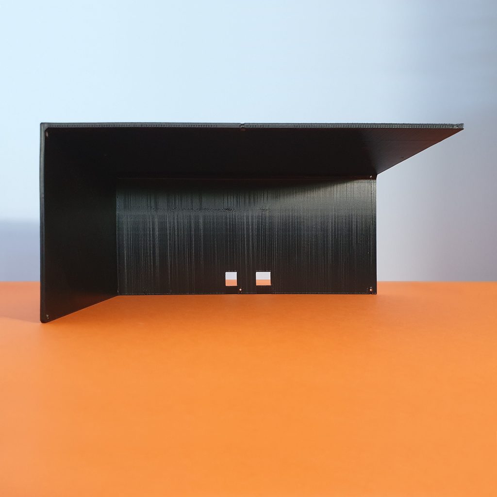
The front side is actually also the base and the right side. All the modules are being mounted to this very part, so you need to make sure to remove anything that is left from the supports.
After the print, it’ll look something like this. Supports cover the whole front side.
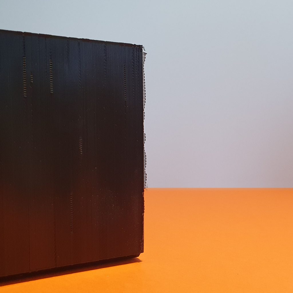
There are lots of supports on the back side as well.
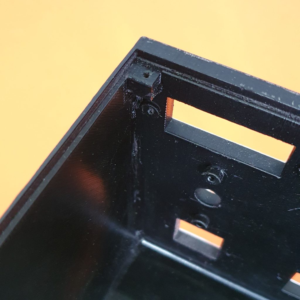
Once the supports are removed, it will begin to take shape!
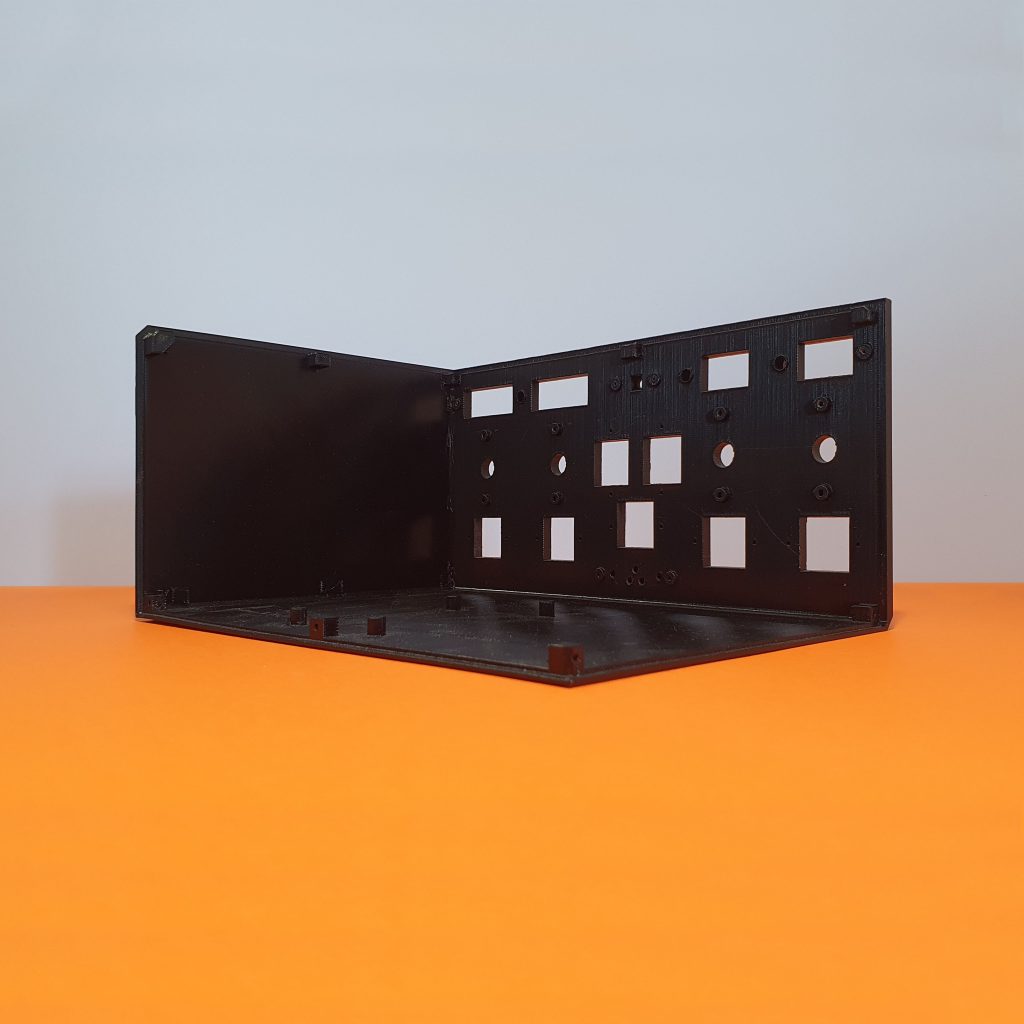
These are usual places where the residual supports tend to last. Make sure to check them thoroughly.
It is recommended to assemble the modules from bottom to top, so you can easily operate with the screwdriver and have some spare space for your hands. It might look like there’s a lot of space inside, but with the increasing number of modules assembled, there won’t be.
We would recommend placing the Indication board with the cable onto the place now. You should also check the front sticker if it fits the actual printed plastics, but don’t use it for now. In the case, you would need to peel it off later on, if some problems occur.
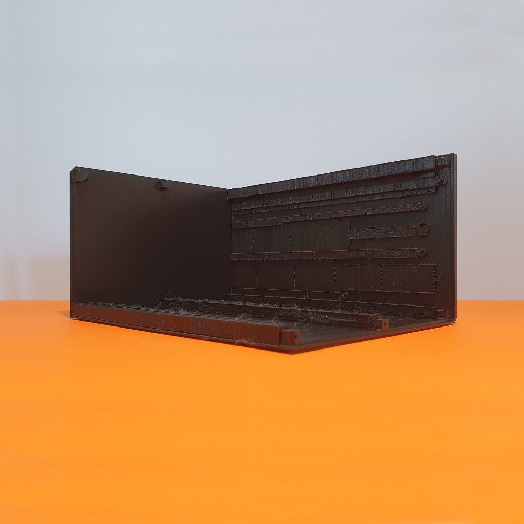
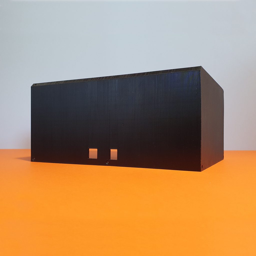
Back cover
The back cover is also the left side and a top cover. This plastic piece is pretty big but has almost no supports on it. Just make sure to be gentle with the two back holes, which are designed for Arduino power supply and USB cable.
Now we start having a bit more fun!
![]()
SimpleFCU preorders are up and running until September 8th!
Functional plastic parts
Functional plastic parts are essential in order to get SimpleFCU running. But don’t worry about a thing, we’ve designed this to make it easy to assemble.
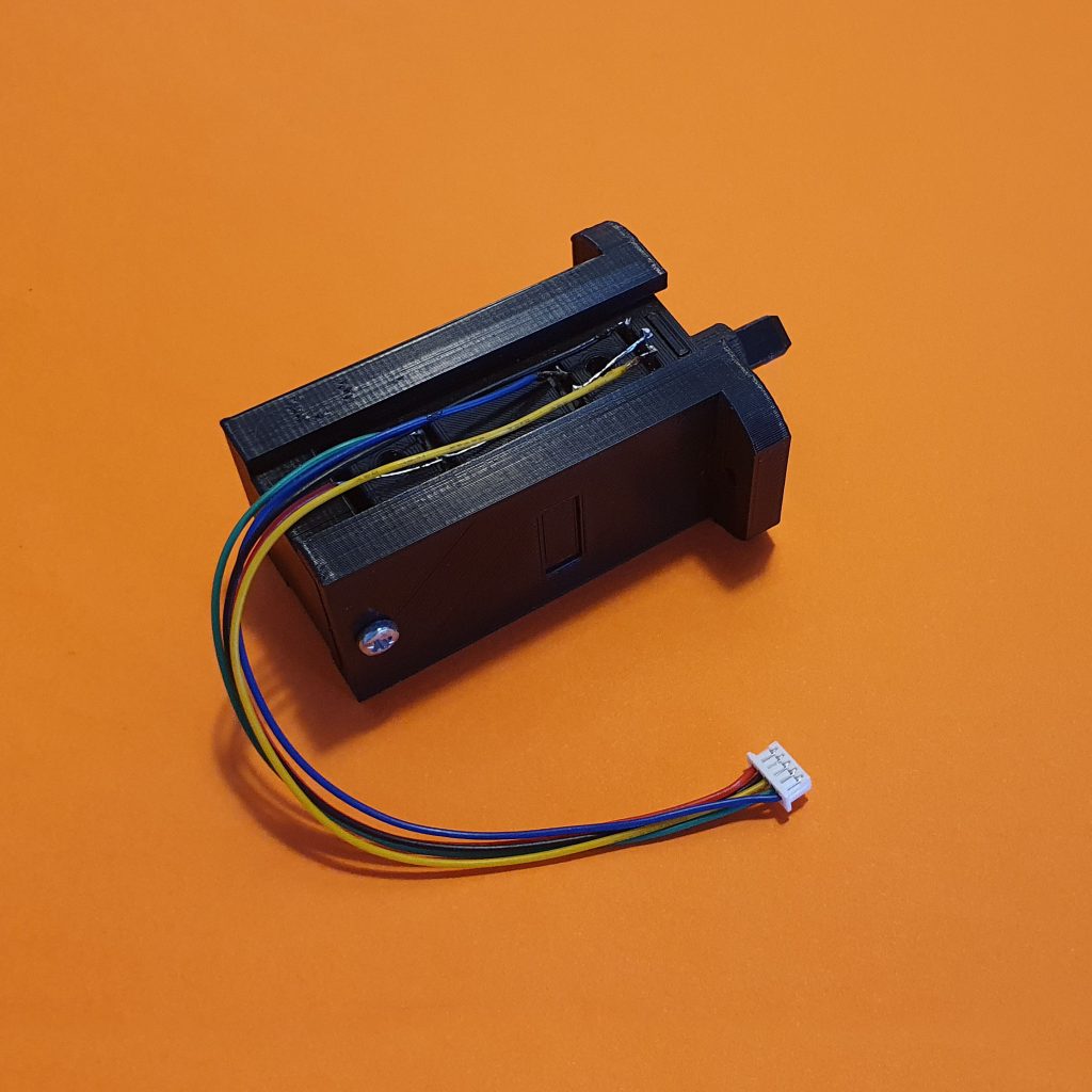
Push&Pull module (PP)
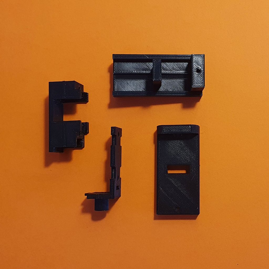
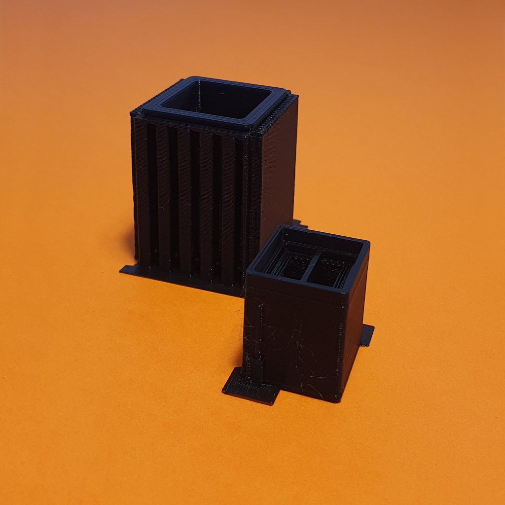
The PP module is made out of 2 inner plastic parts and 2 outer plastic parts. These are fresh out of the 3D printer.
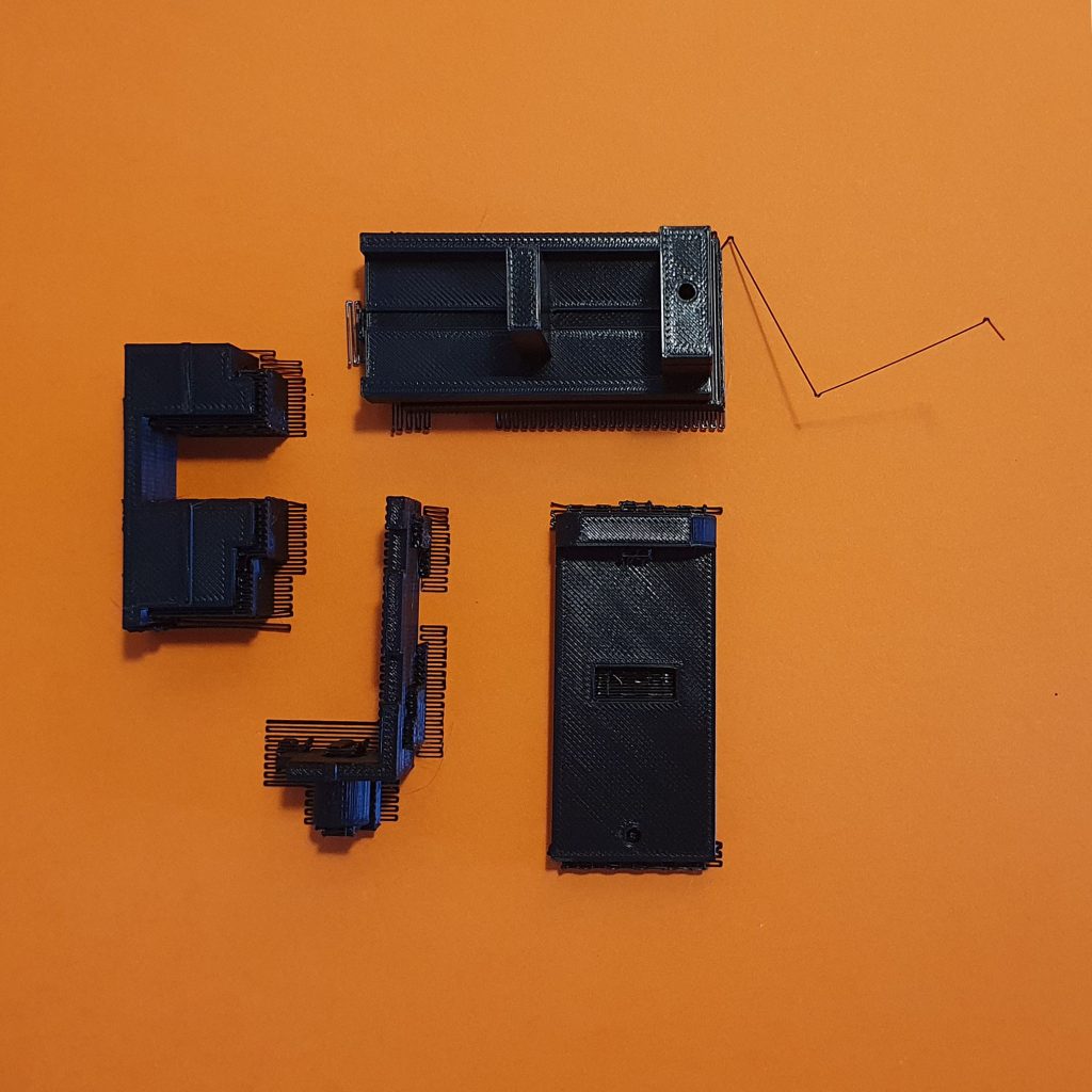
Once all the supports are removed.
The inner plastic parts hold the electrical parts – namely the encoder and two push buttons. There’s a specially designed plastic groove that ensures the plastics won’t move to the sides when using the PP module.
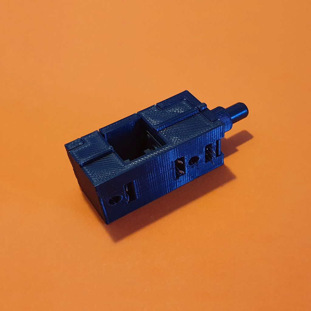
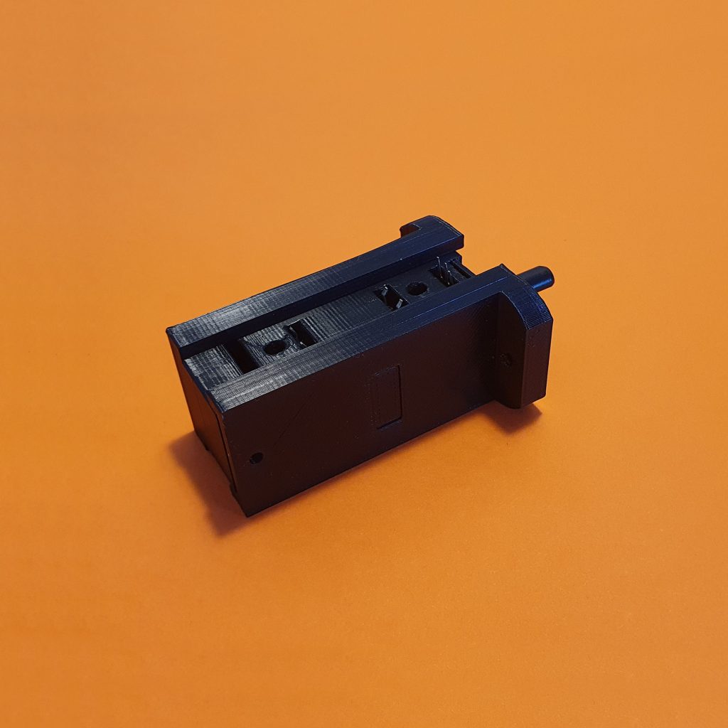
And with two clicks of inner and outer mechanism joined together, voilá!
What about soldering?
You need to solder a few contacts for each PP module. The reason for this is that this has to be done once the components are inside the printed plastics. All you need to do is to use our pre-assembled 5 pin cable and solder it like this.
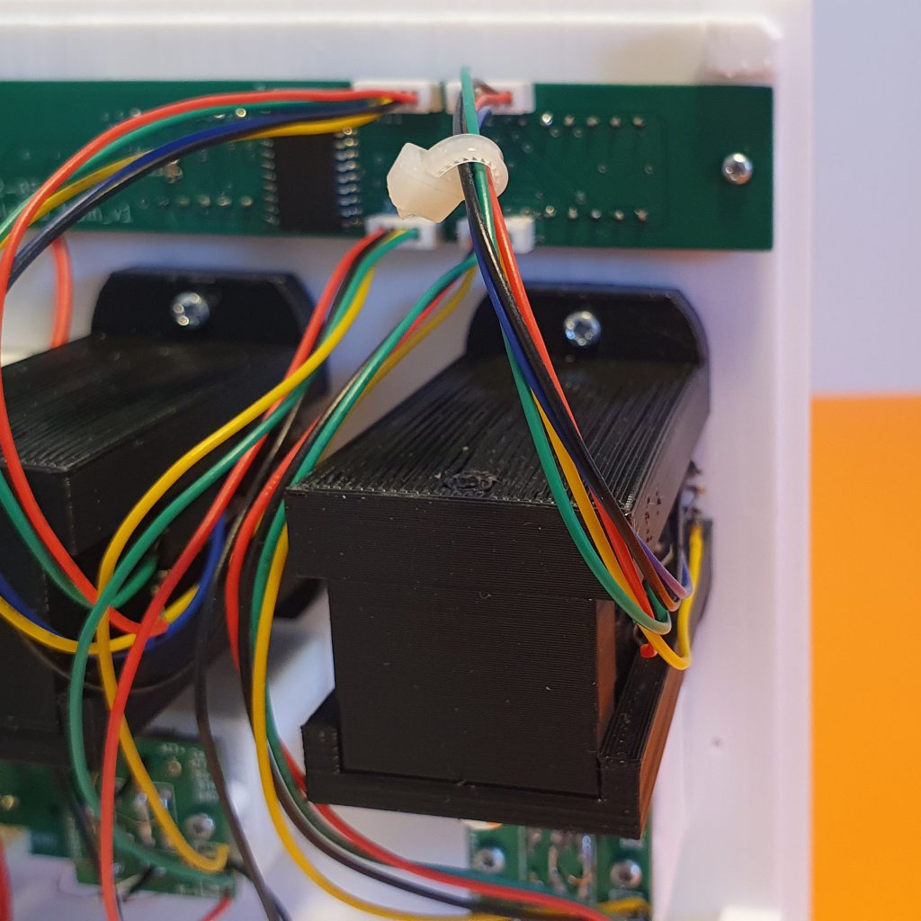
The other side of the cable has a connector, so it goes to the respective 5 pin connector on the Main FCU board. The last thing is to mount these modules on the back of the front side. This can’t really go wrong, as there are printed fixtures for it. Add a few screws and PPs are ready to use! Click and repeat for another 3 modules.
Korry button
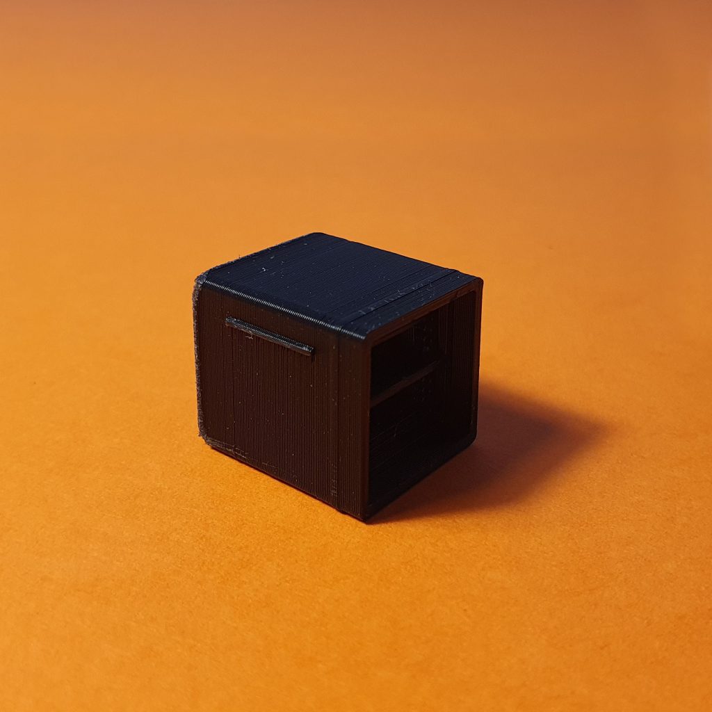
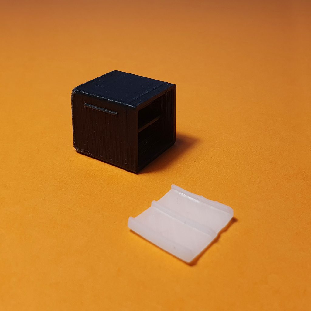
The Korry button assembly is made out of two plastic parts that fit together.
Once all the supports are removed.
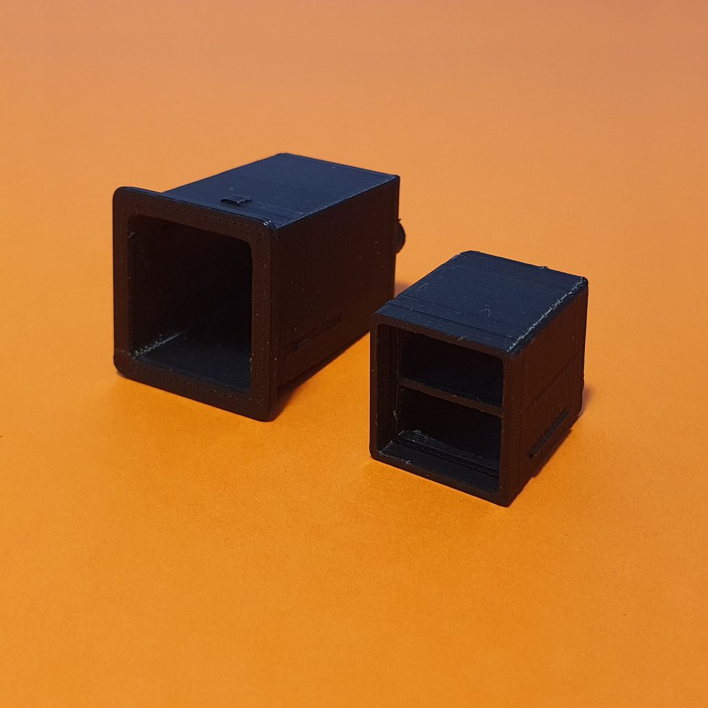
The plastics are designed with an inner lock, so the inserted part of the inner button is fixed in the chassis and thus protected against accidental pulling off.
What about soldering?
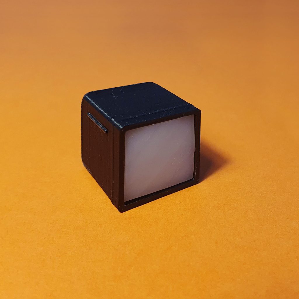
We’ve freshly redesigned the Korry buttons this week and there’s no soldering needed. All you need to do is to insert the pre-assembled PCB into the printed plastic parts and secure it with two provided screws. Is that it? Almost!
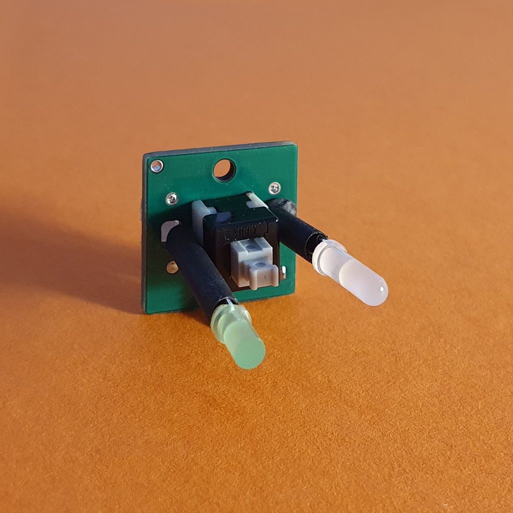
You need to insert the front provided button cover (diffuser) and place a sticker over it.
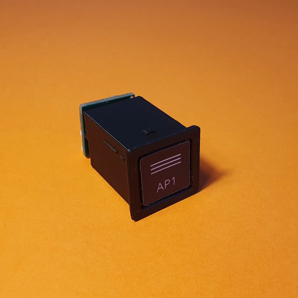
The last thing is to click the 4 pin pre-assembled cable into the Korry board and the Main FCU board. Repeat for the rest 6 Korry buttons and you’re done!
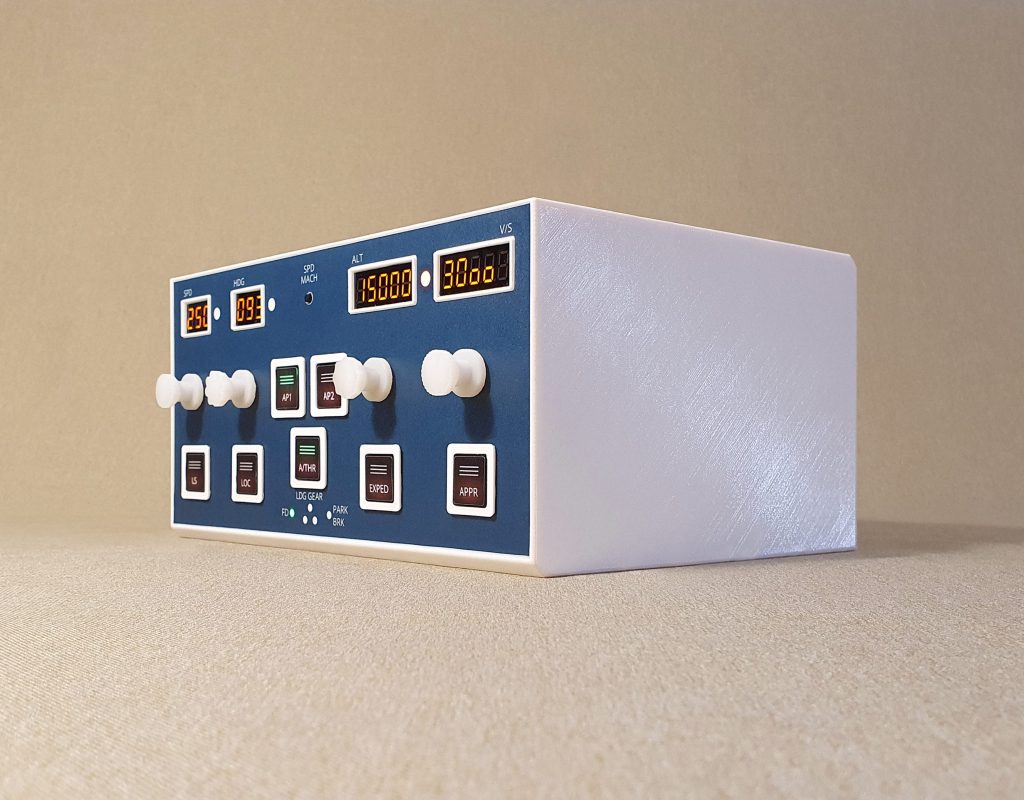
Conclusion
As you’ve seen today, it’s really not a big deal to assemble the printed plastic parts into a working SimpleFCU module. We’re currently working on assembly videos and a full PDF tutorial on how to assemble everything.
This will be available under “My downloads” section for everyone who has secured the SimpleFCU in our currently running preorder approx. 14 days before shipping.
The preorder is running for 30 days only, ending by September 8th.
Grab your SimpleFCU creative edition in our webshop today and secure your position on a shipping list!
We’ve written an extensive blog about the preorder process here.
Let us know in the comments below if you have any other questions ⬇
Safe travels & happy landings ✈️
For the whole SimpleFCU team
Mike
-
Pingback: simpleFCU – Hardware voor de Airbus vlieger